How to programm raw ESP8266-12E Chip
I bought some time ago 5 chips of the popular ESP8266-12E to try to make some of my home sensors more cost effective. These chips were in the drawer from some time but today was time to take them out and start the first design.
Before starting a design base on them I wanted to check if they work, programming them would be a good idea.
I followed the guides described in Source 1 & Source 2
The first big topic was to identify which ESP-8266 Module I did have. After some research in the internet and checking the Silkscreen on the bottom of the module :) I discovered I have the ESP12-E. This module has 22 Pins
| Pin | Name | Description |
|---|---|---|
| 1 | RST | Reset |
| 2 | ADC | 10 bit Analog Input pin for ADC (0…1V()) |
| 3 | EN | Enable Pin Active High |
| 4,5,6,7,11,12, 16, 17, 18, 19, 20 | GPIOs… | General Purpose I/Os |
| 8 | VDD | +3.3V |
| 9 | CS0 | SPI Chip Selection |
| 10 | MISO | SPI MISO |
| 13 | MOSI | SPI MOSI |
| 14 | SCLK | SPI Clock |
| 15 | GND | GND |
| 21 | RX | UART RX |
| 22 | TX | UART TX |
Similar as explained in Source 1 I solder some cables to the module to be able to connect it to a bread board.
In order to program it the Boot Modes is a key concept. Depending on how are the some key pins pull down or up the controller boots up in flashing mode or in normal mode. Once I will create the PCB for the sensor I would use the USB to Serial Interface to automatically set the boot mode. But for this time I need it to do it manually
| Booting Option | Enable Pin | GPIO0 | GPIO2 | GPIO15 |
|---|---|---|---|---|
| Programming Mode | High | Low | High | Low |
| Normal Mode | High | High | High | Low |
| SD Card Boot Up (Not used here) | High | Low | Low | High |
I have taken some screenshots of an schematic in the different modes for better understanding
Programming Mode 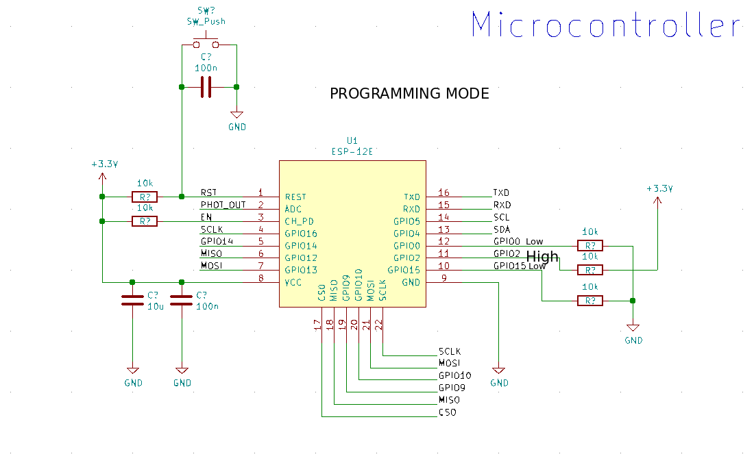
Normal Mode 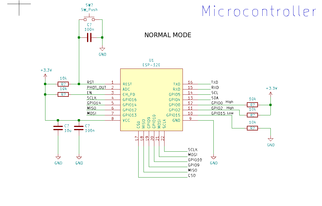
With this information everything is pretty straigh fordward
- Connect the module in a bread board with the schematic shown in Programming Mode
- Power Up the Board and press reset (to be sure it goes in Programming Mode)
- Load the program with your favourite tool (I used Arduino IDE and it worked)
- Power Down the Board
- Change the module configuration with the schematic shown in Normal Mode
- Power Up the board again and the code you upload should be working!
It took some time but at the end it work and I am all set to start with a new development. Wish me luck!